Wednesday 17 December 2014

Show Hidden Lines

Model and detail elements that are obscured by other elements can be displayed using the Show Hidden Lines tool. You can use the Show Hidden Lines tool on all elements that have the Hidden Lines subcategory.


·         Click View tab - Graphics panel - Show Hidden drop-down - (Show Hidden Lines).
·         Place the cursor on an element that is hiding another element, and click to select it.
·         Then select the element that is obscured.

The lines of this element display in a hidden line style through the overlapping element. To change the hidden line style of the element, use the Object Styles tool. The Hidden lines are a subcategory of the element category.


The Remove Hidden Lines tool is the inverse of the Show Hidden Lines tool.
·         To reverse the effects of this tool, click View tab - Graphics panel - Show Hidden drop-down - (Remove Hidden Lines).
·         Select the element that will hide the other element.
·         Select the other element to be hidden.

Tuesday 16 December 2014

Placing Text

If you need to place text in your Revit project, you can just pick a start point and then begin to type. The result will be one long string of text. If you want to get the text to wrap, you will have to manually adjust the text box after placement.


If when you place the text you pick a rectangle, this will create the text box extents and the text will wrap to this box automatically.


Monday 15 December 2014

Creating New Family Types

You can use the Project Browser to create additional family types or edit type parameters. Instead of going into the ribbon and selecting the icon, you can just expand out the heading in the Family list in the project browser and edit the types from there.


You have multiple options,
  • If you right-click on the Family you can create a ‘New Type’ or you can go directly to ‘Edit’ the family.
  • If you right-click on the Type you can ‘Duplicate’ or go to the ’Type Properties’ dialog box.
  • If you double-click on the Type you will open up the ‘Edit Type Properties’ dialog box, where you can duplicate the type or edit some of the parameters.

So next time you need to create a new Family type or Edit some Type parameters, think about the project browser it might be a little quicker. 

Tuesday 9 December 2014

Cut Profile

If you are creating detail views in your model and in specific areas you would like the profile of the element to change without having to manipulate the modelled element. You can use the Cut Profile tool to change the shape of elements that are cut in a view, such as roofs, floors, walls, and the layers of compound structures. The tool is available in plan, RCP, and section views. Changes made to the profile are view-specific; that is, the element's 3D geometry and its appearance in other views do not change.

This tool is used in one-off instances. If you find yourself manipulating the cut profile over and over again for the same object, then you should modify the modelled element. Otherwise you are fudging your model.

The Cut Profile tool is in the View Ribbon.

You can select an individual Face or the Boundary between faces (for elements adjacent one another).


Just select the boundary you would like to adjust and edit the sketch.


When you are drawing the sketch, there is a little blue arrow. Make sure that it is pointing towards the Object you want to show, or you won’t get your material fill pattern to fill the new cut profile.


Monday 8 December 2014

Opening Worksets

When you are opening a Central Project File that contains worksets, you can speed up the process by specifying what worksets you would like to open by selecting the Specify…. tool in the Open Dialog Box. Just hit the down arrow beside the Open button.


This will give you the option of picking the worksets prior to opening. It will save you having to go to the worksets after the file has opened. (As a default it sets them all to open, just review the list and close the one you don’t want!)


Thursday 4 December 2014

Formula - Changing Units

When using formulas in your Revit Families, it can sometimes be troublesome when you are using other parameters to drive formulas that contain different unit types.

For example, if you are creating a parameter that is a number type and you are using a Length Parameter in the formula. The result will be an error ‘Inconsistent Units’


To get these formulas to work, in the formula, just divide the Length Parameter by 1 (the ‘mm’ will automatically appear). Then you will get the correct result.


This process works with other types of Parameter types that use units…..


Monday 10 November 2014

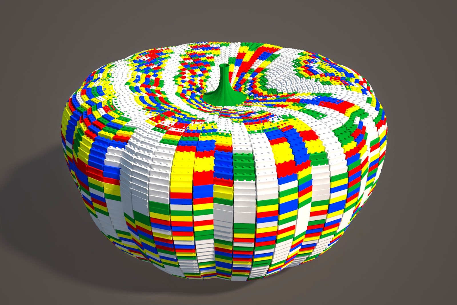
Winning Lego Pumpkin

I am pretty happy with myself. My Lego Pumpkin won in Zach Kron's Parametric pumpkin competition.

http://buildz.blogspot.com.au/2014/11/happy-halloween-vi.html


Worksharing Display

Worksharing Display allows you to distinguish workshared elements in your model. (A great way to see who is interfering with your model.)

The worksharing display is located in the View Control Bar at the bottom of the modelling view.


You can use worksharing display modes to display:

  • Checkout Status - The ownership status of elements.
  • Owners - The specific owners of elements.
  • Model Updates - Elements that are out of sync with, or have been deleted from, the central model.
  • Worksets - Which elements are assigned to particular worksets.

The view below is identifying who the owner is of some of the structural elements.


The Worksharing Display Setting dialogue box (accessed through the Worksharing display Icon) allows you to change the colour representation in the Worksharing display View.


Wednesday 5 November 2014

Reference Plane Identification

When you are using Reference Planes in Projects or Families, it is very useful to name your Reference Planes so that they can be identified later.

If you select the Reference Plane and go to its Properties, you will see that there is a parameter where you can provide a Name.


When you need to set a new work plane, now you have the named Reference Plane in the list.


Monday 3 November 2014

Door Schedule - Adding Rooms

If you are creating a door schedule in your project, some important columns that can be added is the information regarding the rooms that the door is leading to and from.


To access these parameters in your schedule, they aren’t in the default list of available fields. In the bottom left hand corner of the schedule there is a ‘Select available fields from:’ selection box. As a default it is set to ‘Doors’, but you have the choice to change it to ‘From Room’ or ‘To Room’. This will allow you to select additional room based fields to pick from.


Sunday 26 October 2014

Parametric Lego Pumpkin

This is my entry into Zach Kron's 6th Annual Parametric Pumpkin Competition.


I have wanted to enter this Competition for a few years, I finally got my act together and put something together. The following is a bit of a journal of my entry.


Sunday 12 October 2014

Transparent Annotations

As a default on every Revit project transparent annotations should be used. The reason is highlighted below, if dimensions, tags, keynotes, or text are accidentally placed on top of one another than they will block out anything below and errors can occur.

  • The top line of dimensions (Actual Dimensions) is shown with full strings of dimensions indicating the actual dimensions of the layout (too many dimensions for a real life project, but good for this example).
  • The middle line of dimensions (Transparent Dimensions) is shown with transparent dimensions strings accidentally placed on top of one another, but the error can be identified easily with the garbled dimension in the middle.
  • The bottom line of dimensions (Opaque Dimensions) is shown with opaque dimension strings accidentally placed on top of one another, the error is much harder to pick up without scrutinising the dimensions and could have major ramifications on site.


Using Opaque annotations on you project certainly has its place, especially when you have fill patterns on surfaces, having patterns overlapping your annotation can be hard to read. It is just better practice to have it set to transparent as default and change it to an opaque type where required.


Thursday 9 October 2014

Attaching Columns (Profiled Top)

As a default in Revit, when you attach a column to a roof (or another sloped element), the top of the column remains flat. If you would like the column top to be profiled to match the surface above you will need to adjust one of the instance parameters.

Firstly you will need to attach the column to the sloped surface, and then if you select the column, in the properties, go to the ‘Attachment Justification At Top’ and set it to ‘Maximum intersection’. The column will now have the top profiled to the sloped surface. 


You can also set this parameter to ‘Intersect Column Midline’ for the connection to be on the middle of the column.

This works for the base connection as well. Once the column is attached you will be able to change the ‘Attachment Justification At Base’ parameter in a similar fashion.

Wednesday 1 October 2014

Attaching Columns

In Revit you can attach elements like walls or columns to roofs or floors. This process allows you to profile the tops and bottoms of these elements without using the Edit Profile tool.

There is an anomaly to be aware of when attaching columns. Columns remain in their attached position once detached.


In the example below I have a wall and a column that both have the same Base Offset above Level 1. They have been attached to the floor using the ‘Attach Top/Base’ tool.


When I select each element and use the ‘Detach Top/Base’ tool and the ‘Detach All’ option, the column’s base will remain at the floor level, changing the Base Offset to 0. The wall will revert back to its original base offset above the floor level.


This process works the same if the column is attached to a roof. Columns will stay at the attached level once detached.

When attaching walls and columns, the walls are the elements that will change their profile at the top or bottom once attached. Columns will remain flat at the top or bottom, but move up or down to the element that they are attaching to.

Columns don’t have the ability to ‘Edit Profile”, you would have to use a void to profile the top or bottom of columns.

Monday 29 September 2014

Save View as an Image

If you have created a view of your model that you would like to keep for future reference you have 2 options.

The first option is to keep the image inside your Revit Project.

  • If you right click on the view in your project browser, and then you choose ‘Save to Project as Image’. This will bring up a dialog box where you can adjust the view settings. Once you have defined the settings, if you hit ‘OK’ this will create an image of the view and save it in the ‘Renderings’ section of your  Project Browser.


 The other option is to Export the image to outside of the Revit Project.

  • If you click the Revit Application Button (top left hand corner) Export Images and Animations Image. This will bring up a dialog box where you can adjust the view settings. Once you have defined the settings and given it a save location. The image will be created outside of your project.


Thursday 25 September 2014

Project Browser Searching

Ever had too many Views, Sheets, Families, etc…. in your project browser, and it is really hard to find the one that you want? This is where a good naming strategy comes in handy, because you can search your project browser.

If your right click on any of the headings in your project browser, you will see that you have a search option, just type in a keyword in the name that you want and it will highlight in the project browser. (You can actually right click on anything in the Project Browser to get the same function, the Search is just down the bottom of a longer list of options)


Wednesday 24 September 2014

Phase Mapping

When you are working with Phases and Linked models, you need to make sure that all the phases correspond with one another. This means that there should be the same number of Phases in you linked models as well as your project model, and the naming convention should match.

To verify your phase mapping…..

  • Select the Linked Model (in a view where it is visible)
  • Go to the Edit Type Properties
  • Click the Edit button next to the Phase Mapping


This process can get a little more complicated working with consultants, but with good model management and communication, a streamlined mapping of phases can be achieved.

Monday 22 September 2014

Copy and Paste from Linked Files

When you have linked models loaded into your project model, if there is a family you would like to use in the linked file, all you have to do is use the ‘TAB’ button and select the family and then press the ‘copy to clipboard’ tool and then press the ‘paste from clipboard’ to load it into your current project. Easy as that, no need to hunt the family down in a project library….


Sunday 21 September 2014

Tagging in Legends

This is a reminder of some of the limitations that Revit has when you are documenting your projects.

Creating visual Legends in your project is a great way of representing your components, but they do have their limitations. If you want to tag or keynote these elements you find that the only tag or keynote that you can use is the Material Tag or Material Keynote.


The other Tags and Keynotes are visible, but you will not be able to place them in a Legend view.

A workaround for this process is to create a shared material parameter that can be loaded into a Material Tag family and then loaded into your project and assigned to the material of the component. This will bring back some of the functionality of Tagging. I don’t like using workarounds but sometimes it is your only choice…..

Thursday 18 September 2014

Naming Parameters

When naming parameters in your Revit project or family files, we should try never to use symbols in the name. These include the addition ‘+’, subtraction ‘-‘, multiply ‘*’, divide ‘/’, and even the bracket ‘()’ symbols. Revit will allow you to add these symbols to the name but problems can follow later if you start to write formulas.


When you start to create formulas, this is where Revit will start throwing up errors and you will end up not being able to save your dialog box. The names conflict with Revit’s mathematical processes.


So to be safe, try never to add symbols to your Parameter names.

P.S. There are other mathematical statements that can cause conflicts too, like ‘if’and 'not'…… 

Monday 8 September 2014

Extracting In-Place Famalies

Although you rarely need to create In-place Families, there is the occasion where the Project model layout will assist in the set out of your family. Here are a couple of easy ways to create a family while using the project to layout its extents without having the result being an In-Place Family. The trick is to start the family in the project model as an In-Place Family and then extract it to an External Component Family. This can be done using 2 methods.

Method 1: Extracting using Cut and Paste.

When you are creating the in-place family, you first need to pick a Category, give it a name and then you are in the Family editing model, where you can create the modelled family elements. Once you have finished creating the modelled components, before you hit the Finish Model Tick Icon. Just select everything in the in-place family and cut the element out of you model using the ‘CTRL’ + ‘Z’.

Then Go to Revit Application Button and Start a new family, picking the correct template file for your family.


Then simply Paste (‘CTRL’ + ‘V’) the modelled elements into the new family, position them correctly and Save the new family, and now you have a new External Component Family.

Method 2: Extracting using Groups.

Create you model as previously outlined. Then before you finish the model, Group all of the elements, Select the Group and then go to the Revit Application Button Save As Library Group


You will notice that in the file type is saved as family (.rfa).


Now you can save it as an External Component Family.

Both of these methods will result in an External Component Family without having to fill you model with In-Place Families.


Sunday 7 September 2014

Working Views

In your Revit model we create plenty of views of our model to convey our design. A lot of these views are locked down with view templates and view filters to keep them uniform for documentation purposes. This can make it more difficult to carry out normal day to day modelling changes.

An easy way to have a view free from any constraints is to have a working view, this is your messy view, where you can have detail lines, temporary sections, no visibility constraints. These views will never be placed on sheets, so they are free from normal view constraints.

Better still they can be contained in the own section in the project browser.


To set up these views…..
  • Just duplicate an existing view      
  • Rename the new view by prefixing it with a ‘w.’ (this keeps the View Name unique)
  • Then change the View Type to Working. (or create a New Type if it isn’t there)


Thursday 4 September 2014

Purging Families

When you are creating Families for your Revit Projects, always remember to purge your families after you have created them. This will really help in your Project file as all of the extra unused information can quickly add up over the life of a project.

Don’t forget about the nested families too, no point purging the parent family without also doing the nested families.

The purge button is located under the Manage Ribbon.


Monday 1 September 2014

View Templates

Applying View Templates to views is a great way of keeping your model views looking uniform, but keeping track of your view Templates can sometimes be a bit of a task. Here are a couple of tips to help keep track of your view Templates.

To see what View Templates have been applied to Views. Just select the View Ribbon View Templates  Manage View Templates


Sunday 31 August 2014

Revision Numbering Sequence

When we are adding alphabetic revisions to our sheets in Revit it can get a little confusing using letters like ‘I’ and ‘O’ as they look like numbers one and zero. We have the ability to adjust our revision sequence to skip these letters.

Under the manage Ribbon, go to Additional Settings ►Sheet Issues/Revisions 


This will bring up the Sequence Options Dialogue box, where you can take out letters that you don’t want to show.

This will bring up the Sequence Options Dialogue box, where you can take out letters that you don’t want to show.


Tuesday 26 August 2014

Placing Views on Sheets FAST!!!

When you are adding views to sheets, it can take Revit a long time to regenerate the views once they have been placed. Multiply this for an entire project and adding views to sheets can be a very time consuming process.

If you are going to be creating a few sheets, try closing all the Worksets and then add the views. With nothing visible in the views this will dramatically speed up the process. 


If you are using the Grids or Levels to line up the views on the sheets, then you can have the ‘Shared Levels and Grids’ Workset open.