Monday 19 December 2016

Wall Length Adjustment

This is a relatively simple tip, but I was helping a user in the office today and when I adjusted an existing wall using this method, they exclaimed that they didn't know of this functionality....so, just in case you didn't know....

 If you need to adjust the length of an already modeled wall, and one end is going to remain in its original location, select the wall and select the dot at the end that needs to be adjusted holding the left mouse button down, dragging the end of the wall in the direction of the adjustment type in the value of the desired overall length.


Sunday 4 December 2016

Another Interesting Error Message

I just love seeing the obscure warning messages…..we are getting quite a collection from Revit now….


Perhaps when they were writing the code for this one, they had been watching one too many Star Trek Episodes???

Sunday 27 November 2016

Schedule Hidden Fields

Scheduling in your project often calls for some sorting or filtering of the schedule fields. This can call for a bit of schedule magic, especially if you want a particular field to sort or filter the schedule but you don’t want that field to be visible in the final schedule.

This is where you can use a Hidden Field.

In the Example Door Schedule below, I want the schedule to group all of the Doors of the same ‘Construction Type’, but I don’t want the Construction Type to be visible in the final schedule.


To create this schedule ‘Construction Type’ needs to be one of the fields scheduled.

Then you can sort the schedule using the ‘Construction Type’ field. This will get the schedule in the correct order.


If you select the Formatting Tab. Highlight the ‘Construction Type’ field and tick the box labelled ‘Hidden Field’.


This will use the ‘Construction Type’ in the schedule to sort but hide it in the final schedule.


Thursday 10 November 2016

Rotation Center Point Correction

When we need to use the rotation tool in our model, the location of the rotation center point is critical to ensure our rotation is going to give use the correct final result.

When you select an element, pick the Rotate Tool (RO), Revit by default places the rotation point in the center of the element or elements selected. Very rarely do we want it in this location and we have to move it before we execute the command.

We have 3 options to relocate this point.
  1. Click + drag the point in the view
  2. Place Button (Options Bar)
  3. Space Bar (press to position the center point)


Using the Place button or Space bar we just have to click where the center point ought to be. These options are very useful if the center point is not visible in the view.

Using Click + Drag we need to click on the center icon (left mouse button), + drag it to the correct location. 

One thing that is often overlooked is the Copy, in the Options Bar. This will allow you to copy the element and rotate in one command. (Holding down the CTRL key will also activate the Copy option).


Thursday 3 November 2016

Check Ceiling Heights by Colour using Dynamo

I was asked by a Revit User today if there was a quick way of showing the different ceiling heights as a different colour. I initially thought that I could use a “Color Scheme” and try and define the height of the rooms as a different colour?


Before I could begin I found that Ceiling Plans do not support “Color Schemes”. 


I could have used filters but this would take time and every time a ceiling was added at a different height I would have to add or amend a filter.
This was a good opportunity to employ Dynamo to solve the problem. So creating some ceilings at different heights I was able to write a fairly simple script that looks for the “Height Offset From Level” Parameter. Then it applies a colour graphic override to the ceiling.


The good things about this graph are:

  • You can add or delete as many ceilings as you like, Revit will adjust the colour range accordingly (keeping the graph in Automatic will do this instantaneously)
  • You can change the colour range to different colours
  • You can use this to identify other ceiling parameters (just change the “Height Offset From Level" Node to another parameter)
  • This will also work in 3D views (any view a ceiling is visible really)


Sunday 30 October 2016

Complete Project Sheet List

If you have a project made up of a master site and multiple building models, there is a way of producing a sheet list for the entire project, rather than having to produce one for each project model.


Working in the Site Master file, if you create a new Sheet List.


One of the Options is to ‘Include elements in linked files’. This will allow you to produce a Sheet List schedule that contains the Sheets from all of the linked files.


As long as all of your parameters are consistent then you can sort and filter the list to the desired result.

This process is also great for accessing other information from linked files for inclusion in a other master schedules.


Sunday 23 October 2016

Scope Box Visibility

Scope Boxes are a very useful tool to keep extents of views uniform across the project. There are a couple of ways to control their visibility. The obvious method is to utilise the Visibility Graphics Overrides to turn them on or off in views, but this method will control all of the Scope boxes together.


If you would like to control the visibility of Scope Boxes individually and pre-determine the views in which they will appear, this can be controlled in their Instance Properties.

When a Scope Box is selected, in their Instance Properties there is a ‘Views Visible’ parameter. 


If this is selected it will bring up the ‘Scope Box Views Visible’ dialog box, where you can see which views the scope boxes are automatically visible and you have the ability to override their default settings to make them visible or Invisible specifically in each model view.


Wednesday 19 October 2016

Grid Design Option

When you have Grids in your Project, the last thing you want anybody to do is accidentally move them. There are a few ways of locking these away so that they are protected from accidental relocation. You could use worksets or pinning the elements, but a useful Revit feature is using the Design Options.

You don’t need an elaborate naming convention, just create a new Option Set and Option and name them ‘Grids’.


When you go back to your model add the Grids to the Grid Option and they will be secured away. 


The Grids will still be visible but to access them users have to make a conscious choice to activate the Option to make adjustments.

While it still isn’t a fool proof way of securing the Grids, it will provide a good level of security from accidental adjustment.

Sunday 16 October 2016

Structure and Partitions

When you have structural walls and partitions intersecting in your model, it is important to get their intersections looking correct. Revit will always try to join your walls together and usually the resulting intersections is shown correct graphically, in the case of structure and partitions this is where the ‘Disallow Join’ tool can give you a preferred result.

The example below indicates graphically when the walls are automatically joined and when the partition has had the ‘Disallow Join’ applied.


To use the ‘Disallow Join’ just select the wall and right-click on the dot at the end and you will have an option to ‘Disallow Join’.

You will notice that the intersection of the joined walls results in a change in line weight of the structural wall at the intersection, this is not desirable.

When the partition has had the ‘Disallow Join’ the structural walls line weight is continuous and graphically gives the desired result.


So, the moral is to always check the graphical output of your model and don’t settle for what Revit applies automatically.

Sunday 9 October 2016

Associate Family Parameter

When you are working with nested families associating parameters can really help linking your parameters from the nested family into the parent family. The only problem is that unless you know they are there you would miss the Associate Parameter button.


When you select your nested family any of their instance parameters are visible, in the Properties Dialog box the little grey button on the right is the Associate Parameter button. You select this to associate a parameter from the nested family to a parameter in the parent Family.


Thursday 1 September 2016

Dimension Visibility

This is more of an observation of Revit behaviour rather than a tip, but it may be a useful thing to know.

When you have created dimension strings and the elements dimensioned are no longer visible, the dimensions try to adjust accordingly (in some cases).


If I turn the Visibility of the windows off, the dimension string remains but hides the dimensions that relate to the window. The dimensions string can still be selected as one element.


When the windows are turned back on the dimensions will reappear.

If you adjust the View Range of the view, to a range where the doors and windows are no longer visible (moving the cut plane above the head height of the elements). The dimension string still remains intact and visible, even though the doors and windows are no longer visible in the view.


Project Info and Shared Coordinates

When you are working in a Workshared Project, that utilises Shared Coordinates and Linked Revit Models, one side effect is that whenever you alter the location of a Linked file you become The Owner of the ‘Project Info’ Workset in the linked file. Especially if you don’t save the position back or synchronise the file.


So if you open a linked file, even to have a look and accidentally move one of the linked models, you may be getting a call from one of the other Revit users to relinquish the ‘Project Info’ Workset, even if you think you haven’t saved anything.

Revit knows where you have been and what you have been doing!!!

It is watching you right now!!! :)


Thursday 25 August 2016

Computation Height

If you are placing rooms in your Revit model and you have a room that seems to be enclosed on all 4 sides and yet when you go to place a Room, Revit informs you that it is not enclosed. It may be because of the Levels ‘Computation Height’.


Revit identifies the enclosed perimeter of a room at a distance above the level, set by a parameter called the Computation Height. By default the computation height for all levels is set to 0, and usually it works except if you have the base of the walls set above the level, like in the case of a room being set on a plinth or a mezzanine.


If you need to adjust the Computation Height, you have to go to an elevation or section view, select the base level line and look at the Properties palette, under Dimensions, and enter a value in the Computation Height parameter that will raise it up to a level above the base of the walls.


You room now will be enclosed.


If you have sloping walls in your model, be aware that the Areas and Volumes calculated will alter depending on the computation height set.


Thursday 11 August 2016

Rio Olympics Kinetic Sculpture in Revit and Dynamo

In the spirit of the Olympics!!!

I was intrigued by the Kinetic Sculpture that is behind the flame at the Rio Olympics. So I decided to see if I could model it in Revit and get Dynamo to animate it!!!


The model is fairly simple once you get your head around that it is just one "Paddle Element" arrayed around a circle and then each one is rotated slightly to provide the 3D helix like pattern.

The Paddle is an adaptive component that is using 2 hosted points providing rotation in 2 directions.


The Dynamo script provides the input to setup all of the paddles (this could have been done manually, but why bother), and then an integer slider allows the animation of the Paddles.


Finished product below.


Wednesday 3 August 2016

Select by ID

Revit is not just a modelling tool it is a vast database of information, and every piece of modeled information can be identified uniquely by its ID number.

To be able to identify every element by its individual ID number is extremely useful when you run into error messages like this……..


Or when you run a warning report on your model and you need to try clear out the warnings, usually the only way to determine what the warning is related to is through its ID number.


If you need to find in your model elements only identified by their ID number, then if you go to the Manage Ribbon, and select the ‘Select by ID’ tool.


All you need to do now is to type in the ID number (or numbers, use a semicolon between) and Revit will scan the model and select the elements.


Wednesday 20 July 2016

Floors and Sloping Walls

When you have sloping walls in your model, it can be a little difficult to add floors and have their boundary snap to the sloping wall. You just aren’t able to pick the edge of the sloping wall where the floor intersects.

You could go down the path of setting up levels, splitting walls, creating new elements all to try and get this edge to snap to, this will take a long time and often the result isn’t 100% accurate. But, there is an easy way.

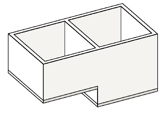
In this example the new floor is set half way up the sloping wall and in the floor sketch creation I was unable to pick the intersecting edge of the floor and the wall. The resulting floor is not ideal.


To get the floor to snap to the edge of the sloping wall, just draw the floor a little bigger than you need. (So that it sticks out from the sloping wall.

Then go to the Modify Ribbon, and pick the Join tool, and join the floor and the sloping wall.


Now you have an edge line where the floor and the sloping wall meet. (There is an edge on the inside too!)

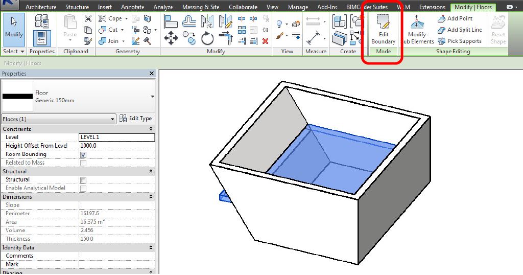
All you have to do now is select the floor, Select the ‘Edit Boundary’ tool.


And using the ‘Pick Lines’ Draw tool. Select the internal edge for the floor. It will put a new line on the edge.


Clean up the floor sketch using the trim, and delete tools, and finish the sketch. You now have a floor that aligns with your sloping wall.


Wednesday 13 July 2016

Symbolic Line Visibility

When you are working with Revit Families, Symbolic Lines are a fantastic way of showing detail without having the entire model represented.

A small restriction to some family types is the Visibility setting, ‘Show only if Instance is Cut’ which will allow you to have the Symbolic Lines appear only if the family is cut in the view. The option is greyed out in a lot of the family categories, especially Generic Models.


If you need the ability to activate this option, here is the solution.

Change the Category of the Family to a Category where the tick box is available. ‘Casework’ works fine. (It is only temporary, so is doesn’t matter about which Category it is, just one that works).


Now if you select the line and go to the Visibility Settings, the ‘Show only if Instance is cut’ tick box is available.


Once the box is ticked, if you then switch the Category of the Family back to its original Category, the Visibility Option will Grey out again but it will remain ticked.


Wednesday 6 July 2016

Family Category?

To have control of your Revit model it is very important that you know the Category for all of your components. An easy way to find out what Category components of your Revit Model are, Autodesk had been rather kind and given you a couple of ways to quickly find out.

If you hover your mouse cursor over a component, and wait a second, Revit will reveal a quick info box that contains Category and Family Name information.


Another method is,

If you select a component and have a look at the Properties dialog box, you will notice that just below the type selector there is a bar that identifies what Category the component belongs to.


Both of these methods will work if you have nested components, you just have to make sure they are shared components.