Wednesday, 9 December 2015

Active Workset

A simple tip that we are all guilty of from time to time!

When you are working in your workshared project, it is always very important to keep an eye on the Active Workset.


When you open your Revit Model the Active Workset can change without your knowing it. When a user changes the current Active Workset to work on his section of work, if he then Synchronizes with Central, their current Active Workset transfers into the Central file.

If they are the last user to Synchronise with the Central file, then the next time you open the Central file and re-create your Local file the Active Workset will change.


The result is, if you don’t notice, you could be putting elements on the wrong Workset……then you (or the Model Manager) need to go and change these elements back to the correct Workset!!!

So the moral of this little tale is to keep an eye on the Active Workset!!!


Wednesday, 2 December 2015

Voids in Families (Part 2)

If you create a void in a family that doesn’t intersect anything, the result will be a free standing void. When you need it to eventually cut an object, you need to move it into position, overlapping with a solid object, you will notice that it doesn’t automatically cut the solid. This is where you need to use the Cut Geometry tool.


Use Cut Geometry Tool, and pick the solid and the void.


If you create a void that intersects the solid objects straight away you will see that the void automatically cuts.

(You can also refer to my previous post about creating the cutting object as a solid first then switching it to a void so that the automatic cutting isn’t activated.)

Monday, 16 November 2015

Controlling Multiple Yes/No Parameters

When you need to control multiple Yes/No parameters in your Revit family, a nice way is to have a controlling parameter. This is the parameter where the user enters an option, which then controls the visibility of other parameters in the family.


The only real limitation with this method of control is that you need to use numerical values. Apart from that you can make the formulas as complex as you like, or keep it simple as shown in the example above.

If the value for the controlling parameter does not correspond to any of the options then none of the tick boxes will activate.

Wednesday, 4 November 2015

Formula 'Not'

When you are creating formulas in your Revit family and you have 2 visibility parameters and you want these 2 parameters to work opposite to one another, this means that when one is ticked the other isn’t and vice versa.

You could go down the path of creating elaborate ‘if’ statements to apply these conditions or you could use a simple ‘not’ statement.


If Parameter A is ticked then Parameter B will be automatically unticked.

Untick Parameter A and Parameter B is ticked automatically.

Sunday, 1 November 2015

Type to Instance Parameter

When you are creating parameters in your Revit Family, here is a quick way of changing a Type parameter to an Instance Parameter. (Especially if in the Family Types dialog box the Modify button is greyed out!)


Close the Family Types dialog box, select the dimension that is assigned to the parameters and look at the Options bar…..

There is a tick box beside the Label parameter option. This will change the parameter to an Instance. Done!


Thursday, 22 October 2015

View Activation

When you are in the Sheets of your project and you have many views overlapping one another, if you are trying to activate a view to edit, it can be difficult to select the view you are after, especially if you are trying to select the views’ outline.

If you just select the view title then you can ‘right-click’ and activate the view for editing. Sometimes it is much easier to highlight the title than the view outline.


Monday, 12 October 2015

Renaming Parameters in Formulas

This tip will put your mind at ease if you have lots of parameters and lots of formulas and you need to do some renaming.

A nice feature in Revit is when you have created your parameters and used some of them in formulas. If you need to rename the parameter, Revit is really kind to you and automatically renames the parameter that is being used in the Formula.

This will maintain the continuity of the formula without having to recompile the formula string. 


Thursday, 17 September 2015

Assembly Tips

Here are a few tips in working in Revit with Assemblies.

1. Warning message displays if the current selection contains elements that cannot be included in an assembly.
The following elements cannot be included in an assembly:

  • Annotations and detail items
  • Assemblies and elements that are already part of another assembly
  • Complex structures (trusses, beam systems, curtain systems, curtain walls, stacked walls)
  • Elements in different design options
  • Groups
  • Imports
  • Images
  • Links or elements in a link
  • Masses
  • MEP-specific elements (ducts, pipes, conduits, cable trays and fittings, HVAC zones)
  • Model lines
  • Rooms
  • Structural loads, load cases, and internal loads

2. Assemblies detect identical geometric configurations, and auto-assign names based on matching criteria. If the assembly be created has the same configuration as an existing assembly type in the model, then the Type name will be read-only, inheriting the Type name of the existing type. Revit then creates another instance of that assembly type instead of creating a new assembly type.

3. An assembly cannot propagate changes to other instances. When you try to edit an assembly instance, other instances of this assembly will not change. Revit will consider this edited assembly instance as different from other instances. A new assembly type is created for this modified instance.

4. An assembly cannot use the Array function.

5. You can create views for an assembly, including Schedule > Part list, Schedule > Material Takeoff, and Schedule > Quantities. You can also create a material takeoff and a schedule for an assembly using View tab > Create panel > Schedules > Material Takeoff.

Difference between “Schedule: Part list” and “Assemblies” schedule is:

  • For an assembly, the Schedule > Part List lists the elements included in one assembly instance.
  • The Assemblies schedule lists all assembly instances in the model instead of the elements in the assembly.

Difference between Schedule > Material Takeoff and Assemblies Material Takeoff

  • Assembly view “Schedule:Material Takeoff” lists the material of the elements included in one assembly instance.
  • Assemblies “Material Takeoff” lists the material of the elements of all assembly instances in the project.

6. After using “Create Views” for one assembly instance, you can’t use “Create Views” for another instance of this assembly type. The “Create Views” button is grey. 
If you want to create more views for this assembly type later, but you can’t find which one you used originally to create views, right-click the assembly type in the Project Browser, and select “Create Assembly Views”.

7. You can add dimensions, tags, and create other views in assembly views, but all annotations, views (section, etc) created inside assembly views won’t appear in regular views of the main model.

8. To delete all instances of an assembly type from the model, in the Project Browser, under Assemblies, select and right-click the assembly type, and click “Delete.”
If you only want to delete an assembly, but keep the elements included in the assembly instance in the drawing area, try following:

  • In the Project Browser, under Assemblies, select and right-click one assembly type, click Select All Instances > In Entire Project.
  • In Modify | Assemblies tab > Assembly panel, click Disassemble.


9. Do not use assemblies, parts, and groups too much in the project. Otherwise, it will degrade model performance.

Wednesday, 9 September 2015

Quick Zoom to Fit

Just a quick one……

When you double click your scroll wheel it performs the ‘Zoom to Fit’ on your current view.

Saves using a keyboard shortcut or the right click dialogue box.


Tuesday, 18 August 2015

Line Based Family Auto-Join

Line based families are a great way of producing flexible Revit components, but there is a feature that may not give you the results you are after.

When you have 2 line based families next to one another they like to automatically join with one another, this is just at feature that occurs in this type of family. The only problem is that there is no disallow join feature (like the wall tool).

The magic number is 32mm, any closer and the components will automatically join.


If you need to have components closer than 32mm you may have to switch to a family with instance parameters, then you can get a close as you want without the components automatically joining.

Monday, 3 August 2015

Plan Region

If you are having trouble getting everything to show in your plan using the standard View Range settings, you always have the option of using a plan region.

While the preference is always to get everything to show using the standard view range, sometimes it is impossible without the use of a plan region.


The Plan Region allows you to set an independent view range to a defined area.


Just select the tool, draw an outline and set a new view range.


Now the object that is outside of the initial view range should be visible.


Sunday, 2 August 2015

Selection Toggle Trick

When you are selecting objects in Revit if you hold the ‘Ctrl’ key down on your keyboard while picking it will add elements to your selection set. (There will be a little plus sign ‘+’ beside your cursor)

If you hold the ‘Shift’ key down on your keyboard then it will subtract elements from your selection set. (There will be a little minus sign ‘-’ beside your cursor)

Now here is the little trick…

If you hold both the ‘Ctrl’ and the ‘Shift’ Keys down while selecting it will toggle between adding and subtracting elements. (There will be a little plus/minus sign ‘+/-’ beside your cursor)

So instead of having to switch between the ‘Ctrl’ and ‘Shift’ key, just get used to holding both keys down when you are selecting elements.

Tuesday, 14 July 2015

Setting Maximum and Minimum Values

When you are creating Families in Revit there is often times where you would like to set maximum and minimum values for a parameter. This can be done using a simple nested ‘If’ statement in the formula.

In the example we would like to specify a maximum and minimum range for a length of an object. For this we will need 2 parameters….

Length – this parameter is the adjustable length of the object in question, this can be set to any amount without limitation. (For example this could be used to describe the distance from the object to a reference point)
Length Actual – This is the actual length of the object that is limited to a maximum and minimum amount.

The Length parameter is manually input (or determined) by the user.

The Length Actual then needs a formula applied to set it maximum and minimum values, in this example we are going to set a maximum amount of 2400 and a minimum amount of 1200.

The formula for Length Actual would read…..

=if(Length < 1200, 1200, (if(Length > 2400, 2400, Length)))

This formula reads….

If the Length is less than 1200 then use 1200, if the Length is greater than 2400 then use 2400, if the Length is between 1200 and 2400 then use the Length value.

(The ‘mm’ units get automatically added by Revit)


Wednesday, 1 July 2015

Formulas - Yes or No Driven by If Statements

When you need to have a Yes or No Parameters enabled by other parameters in your family. Usually you use ‘If’ statements to apply conditions…. Like shown below….

= if (Area  > 1m²)

In the Case of a Yes/No Parameter, you aren’t required to write the ‘if’ part of the formula or the brackets. Just make the statement and Revit will do the rest.

The Example below has 2 sets of formulas both normally would be written with an ‘if’ statement, but in the case of a Yes/No, they are written without. (The top one is an ‘and’ statement requiring both variables to be true for the Yes/No to work.


Thursday, 18 June 2015

Element Transparency

We all know how good a section box is to see inside your model, but if you want to have a quick peek into your model without having to hide elements or evoke the section box tool, than this little tip could help out.

If you select an element in your model it temporarily goes transparent, so to have a quick peek into your model just select one of the walls it will go transparent and you can see inside your model.


This feature is controlled in you Revit Options, and by default it is turned on. You can suppress this feature by going to the Revit Application Button Options Graphics Colors Selection  Semi Transparent.


Sunday, 14 June 2015

Model Fill Pattern Visibility

This is something interesting about how Revit deals with Model Fill Patterns. When you have fill patterns applied to elements in your model, at different scales it will be represented differently, and 1:100 is usually the magic number before visual changes take place.

As the scale increases, Revit will halftone your fill pattern or even change its representation to a solid fill. This is to do with how close the lines are in your fill pattern and the scale of the view.

The Example below is a brick wall, with the model fill pattern to indicate the brickwork. As you increase the view scale it changes from black lines at scales up to 1:100, to halftone at 1:250, to a halftone solid fill at 1:1000.


Different fill patterns with different line spacing’s will give you varying results. It is just good to know that Revit is going to make these changes to your fill, whether you like it or not.

Thursday, 4 June 2015

Selection Filter Groups

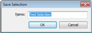
When you are selecting elements and using the Filter tool in the Selection part of the Modify ribbon. You may not have noticed but there are some additional tools alongside the filter icon, Save, Load and Edit. These allow you to create selection sets for future use.


The Save selection, allows you to create a selection set of elements and give them a name so that you can retrieve it later, sort of like a group (without creating a group).


The Load selection allows you to load a previously saved selection set. Just select elements in your model and select the load icon and you will be able to select a previously created set from the Retrieve Filter dialogue box.


The Edit selection allows you to edit the elements in your selection set. You have the ability to add or Remove elements from your selection set.


You will notice that this tools works very similarly to the Group tools, without storing additional groups in your model and leaving all elements individually selectable.

Tuesday, 2 June 2015

Synchronising Faster

When you are in a workshared project, synchronising can be a time consuming process. One way to speed up the process is to synchronise in you ‘Synchronise with Central’ view, this is a drafting view set up especially for synchronising the model.

To help this process, once you have made the ‘Synchronise with Central’ view current, use the ‘Close Hidden Windows’ tool to close all other views of your model.


Thursday, 28 May 2015

Quick Access Toolbar Location

If you don’t already use the quick access toolbar then you should consider it. You can place all of the tools you use all of the time in the one location rather than having to access their location in the Ribbon.

Just right-click on the tool and you will see an option to ‘Add to Quick Access Toolbar’. This will place a shortcut of the tool in the quick access toolbar.


Another tip that may help is to position the Quick Access Toolbar below the ribbon. This will make it more visible, and give you more space to add additional tools (it can get a bit cramped at the top of the screen!)

Just right-click on the Quick Access Toolbar and you will have an option to show it below the Ribbon.


Lastly, you can add other tools to the Quick Access toolbar, like the Type Selector drop down box. This will adapt to the tool/content you are selecting a type from.


Thursday, 7 May 2015

Opening Project - Worksets

A faster way of opening your work shared project is to specify what worksets you would like to open during the file opening process. That way you have total control on exactly what will be visible, and not have to load any information that is not required for you current requirements.

Select the workshared projects you would like to open, then select the down arrow beside the open button. This will activate the Workset options where you can select the worksets you would like to have activated.


Specify is a great option for individually selecting the specific worksets you require, it is also a great choice for file maintenance where you can choose to have no worksets open so the file opens a fast as possible.

Wednesday, 6 May 2015

Wall Joins

Revit will make some great assumptions for you when you are creating you model. One of the assumptions which may not meet you exacting needs is the way Revit will automatically join the walls.

By default Revit will use a butt joint with the wall being more dominant at its start point, and less dominant at its end. The wall joint by display will automatically clean up the intersecting wall layers. You have various options to adjust how the walls join.


To modify the way the walls intersect, select the ‘Wall Joins’ tool (in the Modify ribbon) and select over the intersection in question.


In the Options bar you can change the configuration of how the wall intersects. The Previous / Next buttons adjust the Butt joint, the Miter (Mitre) option is a great way of having all finishes meet up on the corner, without any overlap, Square off allows you to join the walls at 90°no matter what angle they intersect.

You can also Change how the Join is displayed and whether you would like the join cleaned.

In the end, you don’t have to live with the Revit assumptions.

One last tip with altering a walls join, think about how the wall is joining in its entire height, the join at the bottom may not be the same as it is at the top.

Thursday, 30 April 2015

Revit in Feet

Revit is programmed in Feet, even though you have installed a Metric version of Revit. In general you will never really notice, but there are some subtle instances where it becomes apparent....an obvious one is when you are exporting a model for rendering in 3DS MAX, but there are some other instances......like some of the Addins.....

When you are using some of the Addin’s that have been developed in America, because they work in Imperial the units are hard coded into the API. The result is that when we are using them in the southern hemisphere (metric) you get some crazy results and it isn’t enough to just change the units in our project/family.

To get the Addin’s to work properly, a simple conversion parameter formula is required, to get the units set correctly, this can be built into Component Families.

A couple of the Addin’s that require this conversion formula are the ‘DP Randomiser’ and the ‘Set Parameter Values from Image Data’

The example below is for setting a height, but this can be adapted for other parameters.

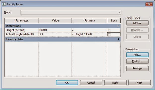
Because the Addin’s are imperial and set in feet, we need to create a parameter that divides the height but 304.8

1 foot = 304.8 millimetres

The ‘Actual Height’ parameter controls the family and the ‘Height’ parameter is controlled by the Addin.


Wednesday, 15 April 2015

Scheduling Available Fields

When you are creating schedules in your project, not all the fields will be available by default. If the field you are after isn’t in the default list you can select additional available fields from the additional options in the bottom left hand corner of the Dialogue box.

In the example below, I am creating a door schedule and I am trying to get some Room based fields to show, they can be accessed from the ‘Select available fields from:’.


Monday, 13 April 2015

Snap Close

When you are drawing an outline in your project or family a handy little keyboard shortcut is ‘SZ’ this is the Snap Close command. This moves your mouse from the last point selected to the start point, thus closing the loop.

This works with any element that is created by selecting points, like walls and sketch outlines.

When you get to the second last point, type ‘SZ’, this will move your mouse cursor to the start point of the sketch and then pick with your left mouse button, (ensure you pick with the mouse or the element won’t be closed).


Sunday, 22 March 2015

Text with Border

If you need to create text with a border around it, you don’t have to draw lines manually, there is an option in the text type properties.

This means that it is part of the text, and if you need to relocate the text or change the content the border will automatically adjust.


Just select the text, go to the ‘Edit Type’ button and in the Type Properties dialogue box, just tick the ‘Show Border’ Parameter.

Remember: This is a TYPE property, so it will change all of the text of that type. You may need to duplicate the type!


Thursday, 19 March 2015

Cutable Families

When you are creating Families in Revit some of the categories are unable to be shown cut in a plan or section views. This means that they will always show up as an elevation.

An easy way to tell which family categories can be shown cut is to refer to the ‘Object Styles’ dialogue box.

All of the Categories that are greyed out don’t show as cut in any views.


Monday, 16 March 2015

Moving Views to a Different Sheet

When you have views placed on sheets in your Revit project, inevitably you will need to move them to different sheets once they have been placed. You might think that you need to delete the view on the sheet, open the new sheet and drag the view onto the new sheet. This can be a time consuming process….but there is an easier way!

If you use your project browser, it can save you a lot of time by using the click and drag. 
  • Expand out the Sheet views you are going to move in your project browser.
  • Select the view you would like to move
  • Hold down the left mouse button and drag it to the new sheet.
  • The sheet view will open and you just need to position it on the new sheet.


Thursday, 12 March 2015

Revit Tip - Hiding Revision Clouds

When you are issuing revisions of your Revit model, they are controlled by the Sheet Issues/Revisions dialogue box, which can be accessed through the Manage ribbon ►Additional Settings. If you want to hide revision clouds from a previous issue, there are a few ways you can achieve this, and they all have individual consequences. The preferred option is outlined below.


No Cloud and Tag, but keep the Revision.

If you want to hide the clouds (and tag) but keep the revision in the schedule in the title block, go to the Manage Ribbon ►Additional Settings ►Sheet Issues/Revisions. This will activate the Sheet Issues/Revisions dialogue box where you can select the revision in question and under the Show column change it from ‘Cloud and Tag’ to ‘None’

This will hide the revision clouds on all the sheets that have this revision, whilst retaining the revision in the schedule.