Monday, 10 November 2014

Winning Lego Pumpkin

I am pretty happy with myself. My Lego Pumpkin won in Zach Kron's Parametric pumpkin competition.

http://buildz.blogspot.com.au/2014/11/happy-halloween-vi.html


Worksharing Display

Worksharing Display allows you to distinguish workshared elements in your model. (A great way to see who is interfering with your model.)

The worksharing display is located in the View Control Bar at the bottom of the modelling view.


You can use worksharing display modes to display:

  • Checkout Status - The ownership status of elements.
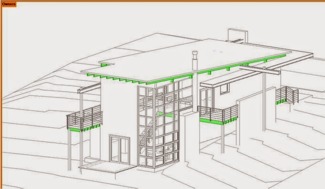
  • Owners - The specific owners of elements.
  • Model Updates - Elements that are out of sync with, or have been deleted from, the central model.
  • Worksets - Which elements are assigned to particular worksets.

The view below is identifying who the owner is of some of the structural elements.


The Worksharing Display Setting dialogue box (accessed through the Worksharing display Icon) allows you to change the colour representation in the Worksharing display View.


Wednesday, 5 November 2014

Reference Plane Identification

When you are using Reference Planes in Projects or Families, it is very useful to name your Reference Planes so that they can be identified later.

If you select the Reference Plane and go to its Properties, you will see that there is a parameter where you can provide a Name.


When you need to set a new work plane, now you have the named Reference Plane in the list.


Monday, 3 November 2014

Door Schedule - Adding Rooms

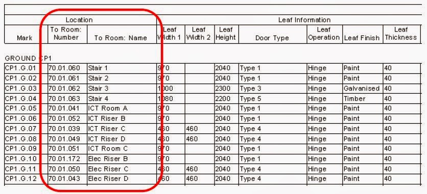
If you are creating a door schedule in your project, some important columns that can be added is the information regarding the rooms that the door is leading to and from.


To access these parameters in your schedule, they aren’t in the default list of available fields. In the bottom left hand corner of the schedule there is a ‘Select available fields from:’ selection box. As a default it is set to ‘Doors’, but you have the choice to change it to ‘From Room’ or ‘To Room’. This will allow you to select additional room based fields to pick from.


Sunday, 26 October 2014

Parametric Lego Pumpkin

This is my entry into Zach Kron's 6th Annual Parametric Pumpkin Competition.


I have wanted to enter this Competition for a few years, I finally got my act together and put something together. The following is a bit of a journal of my entry.


Sunday, 12 October 2014

Transparent Annotations

As a default on every Revit project transparent annotations should be used. The reason is highlighted below, if dimensions, tags, keynotes, or text are accidentally placed on top of one another than they will block out anything below and errors can occur.

  • The top line of dimensions (Actual Dimensions) is shown with full strings of dimensions indicating the actual dimensions of the layout (too many dimensions for a real life project, but good for this example).
  • The middle line of dimensions (Transparent Dimensions) is shown with transparent dimensions strings accidentally placed on top of one another, but the error can be identified easily with the garbled dimension in the middle.
  • The bottom line of dimensions (Opaque Dimensions) is shown with opaque dimension strings accidentally placed on top of one another, the error is much harder to pick up without scrutinising the dimensions and could have major ramifications on site.


Using Opaque annotations on you project certainly has its place, especially when you have fill patterns on surfaces, having patterns overlapping your annotation can be hard to read. It is just better practice to have it set to transparent as default and change it to an opaque type where required.


Thursday, 9 October 2014

Attaching Columns (Profiled Top)

As a default in Revit, when you attach a column to a roof (or another sloped element), the top of the column remains flat. If you would like the column top to be profiled to match the surface above you will need to adjust one of the instance parameters.

Firstly you will need to attach the column to the sloped surface, and then if you select the column, in the properties, go to the ‘Attachment Justification At Top’ and set it to ‘Maximum intersection’. The column will now have the top profiled to the sloped surface. 


You can also set this parameter to ‘Intersect Column Midline’ for the connection to be on the middle of the column.

This works for the base connection as well. Once the column is attached you will be able to change the ‘Attachment Justification At Base’ parameter in a similar fashion.