Wednesday, 20 July 2016

Floors and Sloping Walls

When you have sloping walls in your model, it can be a little difficult to add floors and have their boundary snap to the sloping wall. You just aren’t able to pick the edge of the sloping wall where the floor intersects.

You could go down the path of setting up levels, splitting walls, creating new elements all to try and get this edge to snap to, this will take a long time and often the result isn’t 100% accurate. But, there is an easy way.

In this example the new floor is set half way up the sloping wall and in the floor sketch creation I was unable to pick the intersecting edge of the floor and the wall. The resulting floor is not ideal.


To get the floor to snap to the edge of the sloping wall, just draw the floor a little bigger than you need. (So that it sticks out from the sloping wall.

Then go to the Modify Ribbon, and pick the Join tool, and join the floor and the sloping wall.


Now you have an edge line where the floor and the sloping wall meet. (There is an edge on the inside too!)

All you have to do now is select the floor, Select the ‘Edit Boundary’ tool.
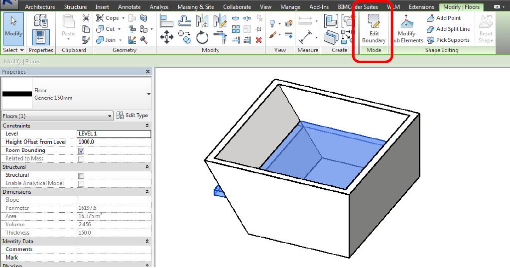


And using the ‘Pick Lines’ Draw tool. Select the internal edge for the floor. It will put a new line on the edge.


Clean up the floor sketch using the trim, and delete tools, and finish the sketch. You now have a floor that aligns with your sloping wall.


Wednesday, 13 July 2016

Symbolic Line Visibility

When you are working with Revit Families, Symbolic Lines are a fantastic way of showing detail without having the entire model represented.

A small restriction to some family types is the Visibility setting, ‘Show only if Instance is Cut’ which will allow you to have the Symbolic Lines appear only if the family is cut in the view. The option is greyed out in a lot of the family categories, especially Generic Models.


If you need the ability to activate this option, here is the solution.

Change the Category of the Family to a Category where the tick box is available. ‘Casework’ works fine. (It is only temporary, so is doesn’t matter about which Category it is, just one that works).


Now if you select the line and go to the Visibility Settings, the ‘Show only if Instance is cut’ tick box is available.


Once the box is ticked, if you then switch the Category of the Family back to its original Category, the Visibility Option will Grey out again but it will remain ticked.


Wednesday, 6 July 2016

Family Category?

To have control of your Revit model it is very important that you know the Category for all of your components. An easy way to find out what Category components of your Revit Model are, Autodesk had been rather kind and given you a couple of ways to quickly find out.

If you hover your mouse cursor over a component, and wait a second, Revit will reveal a quick info box that contains Category and Family Name information.


Another method is,

If you select a component and have a look at the Properties dialog box, you will notice that just below the type selector there is a bar that identifies what Category the component belongs to.


Both of these methods will work if you have nested components, you just have to make sure they are shared components.

Sunday, 26 June 2016

Display Model

A quick way of altering the visibility of modeled elements in a Revit Project is to use the View Properties, Display Model parameter. This will allow you to alter the appearance of all Model elements, leaving the Detail elements unchanged. All without having to alter the Visibility Graphics dialogue box.

In your orthographic views properties, the Display Model parameter allows 3 settings.

Normal – which will show the modeled elements as specified in their Object Styles and Visibility Graphics.

Halftone – sets a halftone appearance to all modeled elements.

Do not display – will turn off every modeled element, leaving just the detail items. This is a great option to see what has been modeled and what is detailed.


Friday, 17 June 2016

Snap Increments

When you create, place or relocate elements or components in your Revit model, Revit uses a predefined set of snapping dimensional increments. For example, when you are drawing a wall and you move your mouse from the start point to the end, you will notice the temporary dimensions increasing be certain amounts, these are the Snap increments.


If you would like to adjust the snap Increments, go to the Manage Ribbon, and select the Snaps tool. This will bring up the Snaps Dialog Box.


You can adjust the Snap Increments for Length and Angular control. You can add as many increments as you like, they just need to be separated by a semicolon.

The different numbers help you control the increments when you are zooming in your views. For example, if you zoom in on your model to look at a detail, then Revit will adopt a smaller value, if you zoom out in the same view it will adopt a bigger increment value. It works off a screen value of 2mm. (There is a little tip on how it works at the top of the dialogue box, under the Dimension Snaps title.)

Sunday, 12 June 2016

New Plan View Creation

When you need to create additional plan views of your Revit model, the temptation is to find a view that is similar and right-click on the view name in the project browser and Duplicate the view, either with detailing or without.

Whilst this method can give you exactly the result you are after, there may be parts of the model that have been overridden in the view which you may not know about, it is often better to start with a fresh plan view and apply the specific view template to give you the finished view.

To create a new plan view, go to the ‘View’ ribbon and select the ‘Plan Views’ tool. This will allow you to select the type of view you require.


The resulting dialogue box is usually blank when it appears which makes it a little difficult to create a new view. There is a tick box at the bottom ‘Do not duplicate existing views’, just untick it and you will be able to select the Levels available.


This will give you a fresh plan view which you can now apply the correct view template.

You can still use the right-click, duplicate view, this process just gives you another option.


Saturday, 28 May 2016

BIM Words to Live (Work) by

I saw this the other day and thought it was a great way to think about how BIM works in our industry....

"Manually doing something more than once is for insane people"